Thomas Green

Soft robotics

A soft robot that installs fibre through buried duct

Laying fibre-optic cable into existing underground duct is slow, and the ducts are rarely clear. We built a soft robot that everts its way along them instead.
Context
Liberty Global, Technology & Innovation
Role
Co-led ideation and prototyping
Period
2022 to 2024, Zurich
Status
Patent-pending, in production and testing
Advancing along duct that already has cable in it, on a test platform. Occupied duct is the normal case in a live network, and it's the worst case for a pull, because every cable already in there is another surface to drag against.
Working around a 90° elbow.
Pushing a loose blockage ahead of the tip.
Carving through compacted silt, shifting it against the wall instead of clearing it entirely.
Following a winding path in the open, with nothing pushing from behind.
Extending vertically, where a pulled cable fights gravity along its whole length.
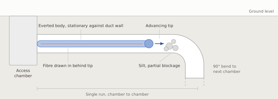
Cross-section of a buried duct. A soft robot everts from an access chamber along the duct, past silt and partial blockages, towards a 90 degree bend into the next chamber. The fibre is drawn in behind the advancing tip.
Deployment in buried duct. The robot enters at one access chamber and everts along to the next, drawing fibre in behind the tip.
3prototypes built in nine months
200+ mtraversed in a single run of live duct

The problem

A telecoms group with a fibre rollout to deliver has a lot of duct already in the ground, and reusing it is far cheaper than digging. The catch is that nobody knows what's inside. Ducts laid decades ago silt up, partially collapse, and take bends that a rigid rod won't follow. Conventional installation pushes or winches cable through. That needs pulling force at one end and tolerates very little friction, so it fails on the routes that are most expensive to dig up.

Every failed pull turns into an excavation, which is where the cost and the delay are.

Why a growing robot

A vine robot avoids the friction problem because nothing slides. The body everts from the tip, so the material already inside the duct stays where it is while the tip extends forwards. Nothing drags along the duct wall, so the force needed doesn't climb with distance the way a pull does. The tip can also work its way past a partial blockage instead of jamming against it.

The behaviour is well established in research, but very little of that work had been aimed at buried telecoms duct at the lengths a real route needs.

What I did

I co-led the idea from the start and ran the prototyping. Over roughly nine months we built three prototypes, 3D printed and machined in-house, each one answering the failure we had hit with the last. The early builds answered whether the robot would evert at all. The later ones dealt with what makes it deployable: getting round bends, dealing with debris, and retracting cleanly when a run has to be abandoned.

Once it held up on the bench we took it into the field, into live duct, not a clean test rig. The best run covered more than 200 metres in a single continuous traversal. We demonstrated the robot to the Group CTO, which secured the backing to take it further.
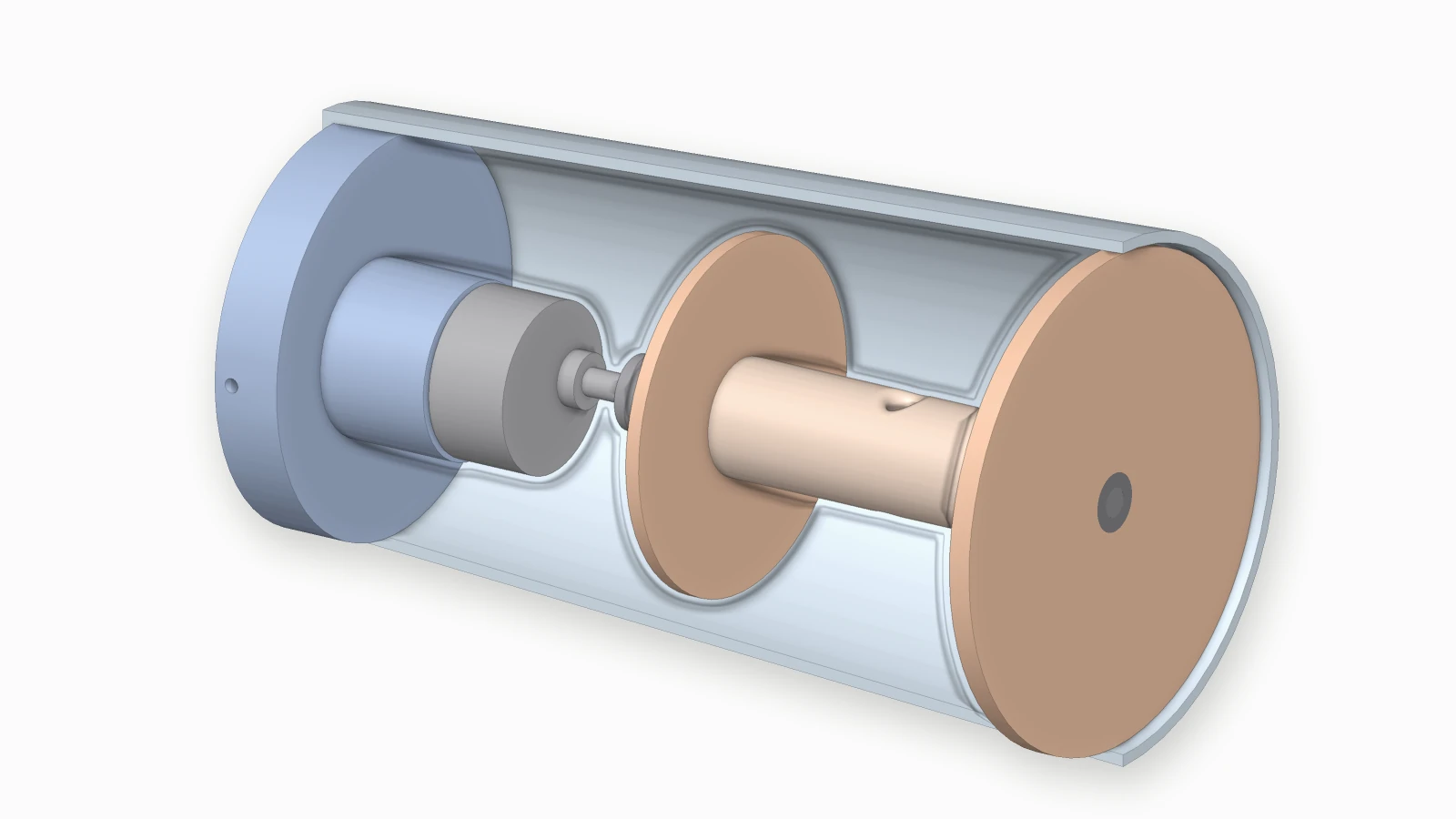
Cutaway render of the first launcher: a sealed cylindrical vessel sliced lengthwise, with a motor mounted on the end plate driving a shaft that carries a spool of tubing along the length of the vessel.
The first launcher, cut away along its axis. A motor on the end plate drives the spool of tubing through a shaft, inside a sealed cylindrical vessel.
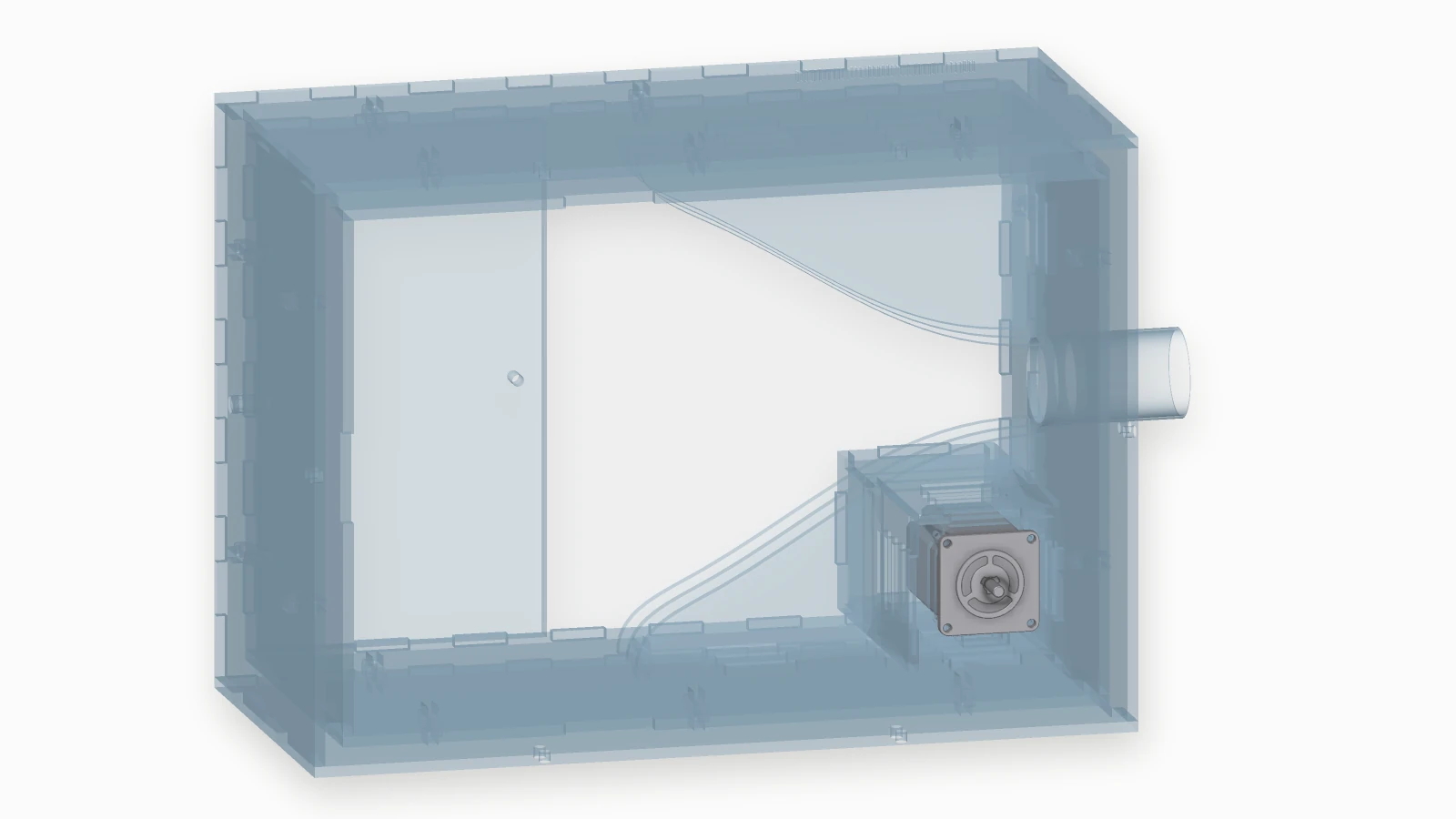
Cutaway render of the second launcher: a clear acrylic box with the near side panel removed, showing a tubing spool, a curved guide leading to an exit port on the right, and a stepper motor driving the spool.
The second, with the near panel removed. Laser-cut acrylic rather than a turned vessel, with the tubing guided to a single exit port and a stepper driving the spool.
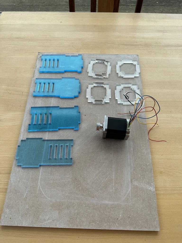
Laser-cut acrylic parts laid out on an MDF board, four blue side panels and four clear motor-mount frames, next to a stepper motor with its wiring loose.
Laser-cut acrylic parts and the stepper for the second launcher, before assembly.
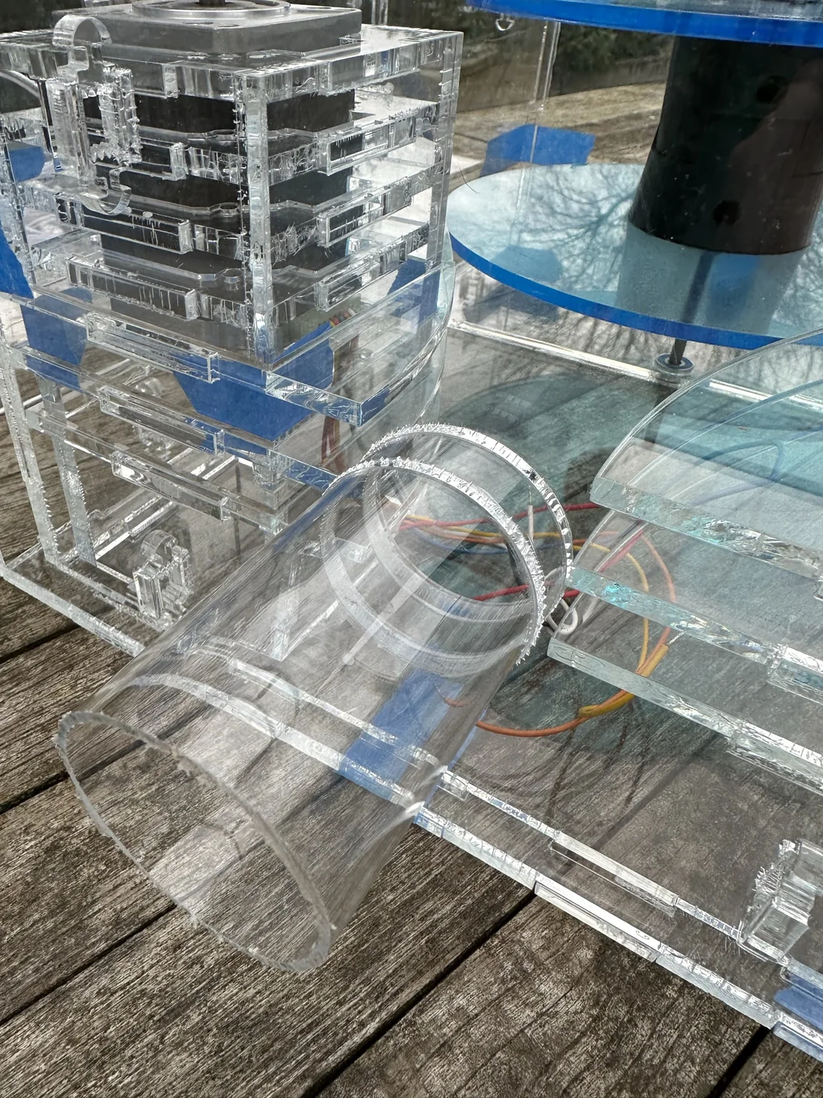
The second launcher in clear acrylic on a wooden deck: the stepper motor in its laser-cut mount, the blue spool discs behind it, and the clear exit tube at the front.
The second launcher as built. The spool sits inside the acrylic housing and the tubing leaves through a single exit port.
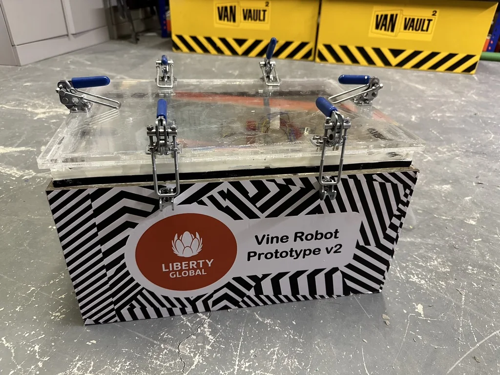
The second prototype closed up: an acrylic lid held down by steel toggle clamps onto a vinyl-wrapped body carrying a Liberty Global logo and the label Vine Robot Prototype v2.
The second prototype as built. The lid seals against a gasket under toggle clamps, so it can be opened between runs and still hold pressure.
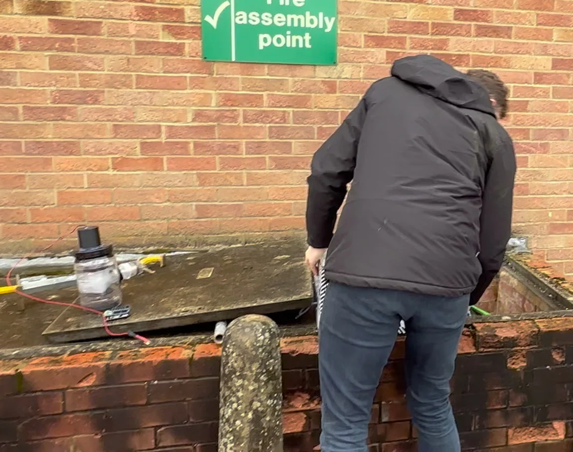
An access chamber outside a building with its concrete lid levered aside, a spade resting nearby, and an engineer leaning into the open pit. On the slab beside them sits the deployment unit with hoses and wiring running down into the duct.
A live access chamber during the field trials. The duct being tested is the duct already in the ground, in whatever state decades of service have left it.

Where it went

Demand from the operating companies pushed it into productionisation, and it's now in production and testing across them. A patent application covering the work was filed by the company and is pending.

What I would do differently

We characterised the robot mostly by whether a run succeeded. That was the right call for proving the concept quickly, but it left us short of the instrumented data that would have made the design iterations faster and the productionisation handover cleaner. If I ran it again I'd build the measurement in from the first prototype, not the third.

← All projects