Thomas Green

Controls · Embedded systems

A retrofit robot that operates a car's pedals

Instead of replacing a vehicle's control systems, this robot sits where the driver's feet go and works the pedals directly, so a conventional car can be automated without touching its wiring.
Context
MEng group design project, Southampton
Role
Actuator design and closed-loop control
Period
Final year, MEng Mechatronic Engineering
Code
automotive-driving-robot
Report
Design journal summary (PDF)
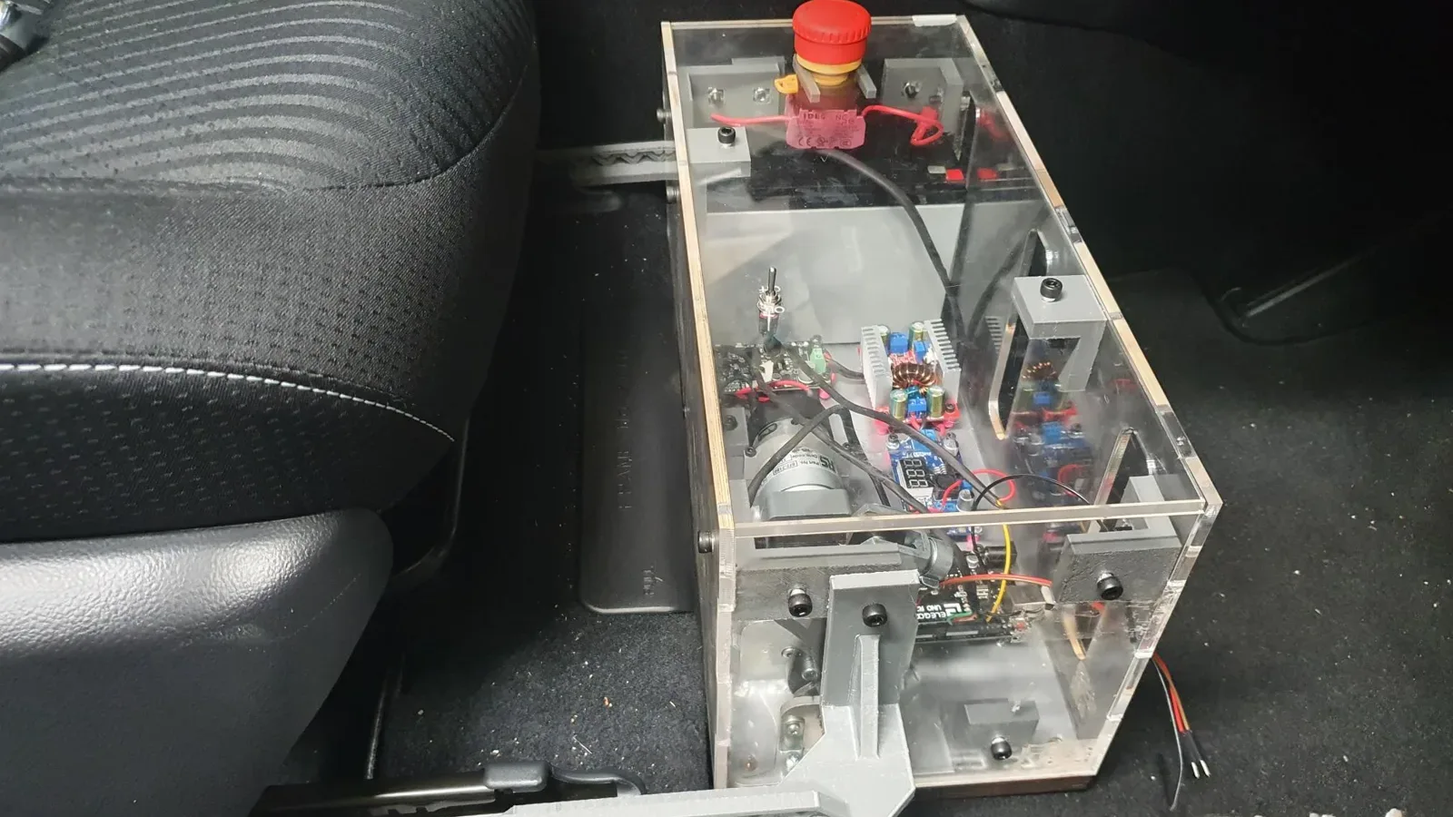
The finished rig cycling a pedal on its test plate. The electronics sit in the acrylic enclosure at the back of the baseplate.
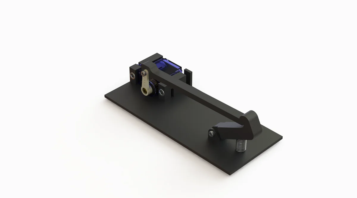
The assembly, built up part by part. Everything mounts to a single baseplate that drops into the footwell, with the output arm reaching across to the pedal.
Three-quarter CAD render of the pedal actuator: a flat black baseplate carrying a compact motor and linkage at one end, with a long arm reaching to a pedal bracket at the other.
The linkage that reaches the pedal.
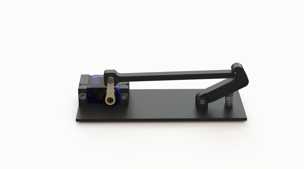
Side elevation CAD render of the same assembly, showing the low profile of the baseplate and the height of the arm above it.
Side on. Height was constrained by the footwell.
The robot installed in the footwell of the test car, a Prius plug-in hybrid: the acrylic enclosure fixed to its baseplate with the output arm reaching down towards the pedal.
Installed in the test car, a Prius plug-in hybrid. The baseplate sits where the driver's feet would go.
Commissioning in the car, tethered to a laptop.
114 ms10 to 90 per cent rise, rest to full travel
0.2%overshoot on a full-scale step
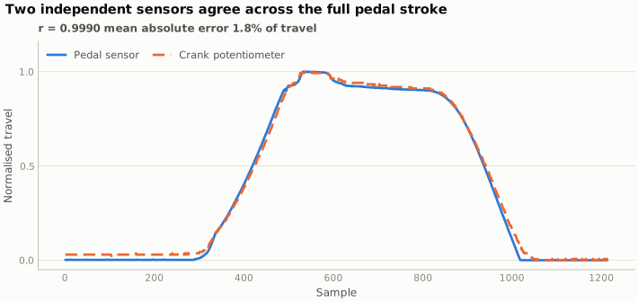
r = 0.999agreement between two independent position sensors

The problem

Testing autonomous driving logic normally means a vehicle built for it. That's expensive, and it rules out testing on the enormous number of conventional cars already on the road. A retrofit actuator that presses the pedals is a way around this: it needs no access to the vehicle's own control network, it can be moved between vehicles, and it can be removed entirely afterwards.

A driver's foot is fast, precise enough, and it feels its own position. Replacing it mechanically means solving position sensing, force delivery and closed-loop control in a package that fits in a footwell.
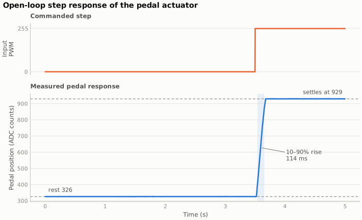
Two-panel plot. The top panel shows a commanded PWM step from 0 to 255 at three and a half seconds. The lower panel shows the measured pedal position rising from 326 to 929 ADC counts with a 10 to 90 per cent rise time of 114 milliseconds and effectively no overshoot.
Full-scale step command against measured pedal position. The actuator covers the full pedal travel in 114 ms with no meaningful overshoot.

Characterising the actuator

The plant here is awkward: a motor driving a linkage against a pedal with its own return spring and a non-linear feel. A controller can't be tuned for that without measuring it first, so the first job was system identification rather than control.

I ran a family of excitation signals through the actuator and logged the position response: steps at several amplitudes, ramps, random square waves and pseudo-random binary sequences at a range of dwell times. The PRBS runs are the useful ones for fitting a model, because they excite a broad band of frequencies without driving the actuator beyond what the mechanics can follow.
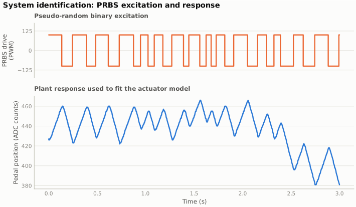
An excitation run on the bench, with the response logged from the position sensors.
Two-panel plot. The top panel shows a pseudo-random binary drive signal alternating between plus and minus 125 PWM with varying dwell times over three seconds. The lower panel shows the corresponding pedal position response oscillating between roughly 380 and 470 ADC counts.
Pseudo-random binary excitation and the resulting motion. The dwell times vary, so the run covers a band of frequencies instead of the single one a fixed-period square wave would excite.

Trusting the position signal

Closed-loop control is only as good as the feedback. The pedal sensor sits on the pedal itself, so it measures the quantity that matters, but it's also exposed and its zero moves as the mechanism is disturbed. I cross-checked it against a potentiometer on the actuator crank, which is mechanically protected but only measures the pedal position indirectly through the linkage.

Across a full stroke the two agree to within about two per cent of travel. That makes the crank signal a usable redundant channel, and a disagreement between the two a fault indicator, not noise.

Line chart with two series over 1200 samples of normalised pedal travel. The pedal sensor and the crank potentiometer track each other closely through a press, a hold and a release, with a correlation of 0.9990 and a mean absolute error of 1.8 per cent of travel.
The pedal sensor against the crank potentiometer through a press, hold and release. Correlation 0.9990, mean absolute error 1.8 per cent of travel.

What broke

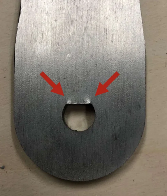
Two things broke, and both were mechanical, not electrical. The gearbox developed enough backlash to be visible in the position trace as a dead band around every direction reversal, which matters because pedal modulation is mostly small reversals, not full-travel sweeps. And a crank arm cracked at the pin slot, where the section is thinnest and the load is highest.
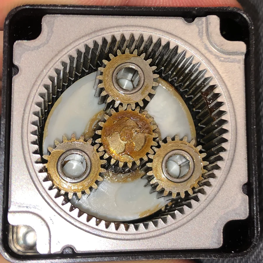
An opened planetary gearbox photographed from above, showing a large internal ring gear, three planet gears and a central sun gear, with grease spread across the faces and visible wear on the tooth flanks.
The gearbox opened up. Wear on the tooth flanks is where the backlash came from.
Close-up of a machined metal crank arm with a rounded end and a pin slot, with two red arrows pointing at cracks propagating from either side of the slot.
Cracks propagating from both sides of the pin slot, arrowed. A stress concentration we designed in and did not catch.

Neither is unusual for a first build, and both only show up once the rig has done real cycles. The instrumentation caught the backlash before the crack appeared: the dead band showed up in the sensor trace while the arm still looked fine.

What I took from it

Measuring the plant before touching the controller is the habit that stuck. It cost time at the start and saved more later, because tuning stopped being guesswork. It's also why I regret not instrumenting the vine robot earlier.

← All projects